•  

    A SUCCESSFUL EVENT AT THE

    IEC TC 37/SC 37A PLENARY MEETING IN MILAN BY ZOTUP S.r.l.

    Read more in the  COMPANY NEWS

    Leonardo Tour 16 300px

  •  

    DO YOU KNOW HOW TO CHOOSE THE RIGHT SPD?

       Download our WEBAPP free of charge

    webapp gallery en 1

  • 1
  • 2
  • Default
  • Title
  • Date
  • Random
  • Now available for download the CATALOGUE ZOTUP 2020/2021, with new products and interesting news about SPDs. 

    +
  • Find the proper Surge Protection Device
    Download the New ZOTUP Webapp
    FOR FREE

    +
  • Visit our Facebook fanpage .... you'll discover events, news and updates. Stay tuned!!

    +
  • ZOTUP is a new SPD with progressive indication of performance. It's easier to control progressively the SPD level of efficiency and then to plan its replacement. 


    +
  • Give a look to the new video preview. ZOTUP a brand new range!

    +
  • ZOTUP is the new SPD that allows you not to use fuses for a quicker and easier setup.


    +


The operation of surge arresters in an electrical system can be compromised, completely or partially, by the use of inappropriate conductor cables. The standard IEC 60364-5-534 offers important information about minimizing the voltage loss in the cables. To understand the importance of this issue, consider that the impulse current due to a lightning strike can increase at 10 kA/μs. In this instance the inductive components of circuit become dominant and can result in a voltage drop of 1 kV per meter.


installationadvices 


The ‘V’ connection in many surge arresters is facilitated by the presence of doubled terminals. In some instances, this type of connection is not possible because of the associated high current and the relative cables cross-section. It is possible to optimise the wiring thanks to the CP series accessories.


 installationadvices 1 

installationadvices 2


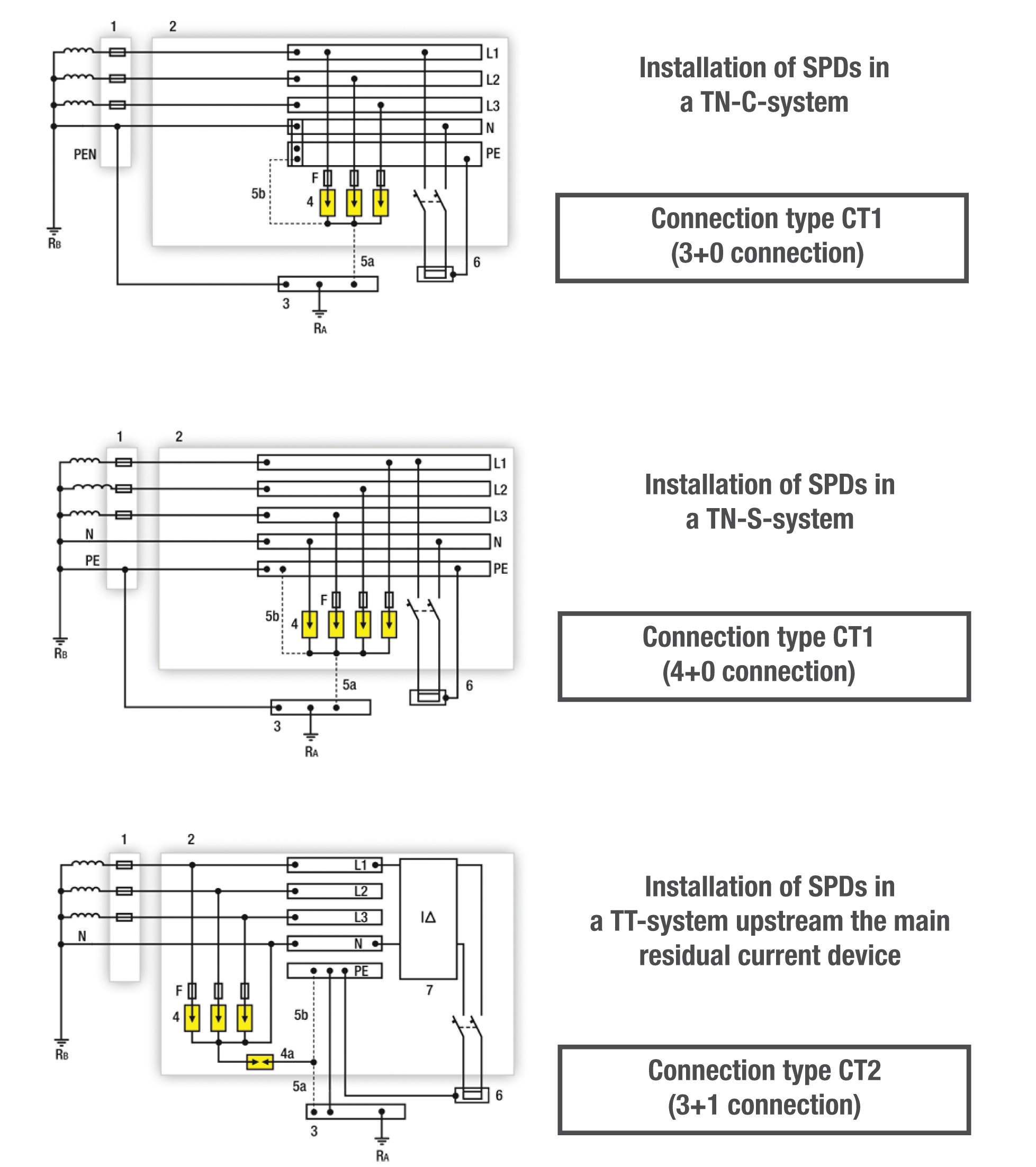
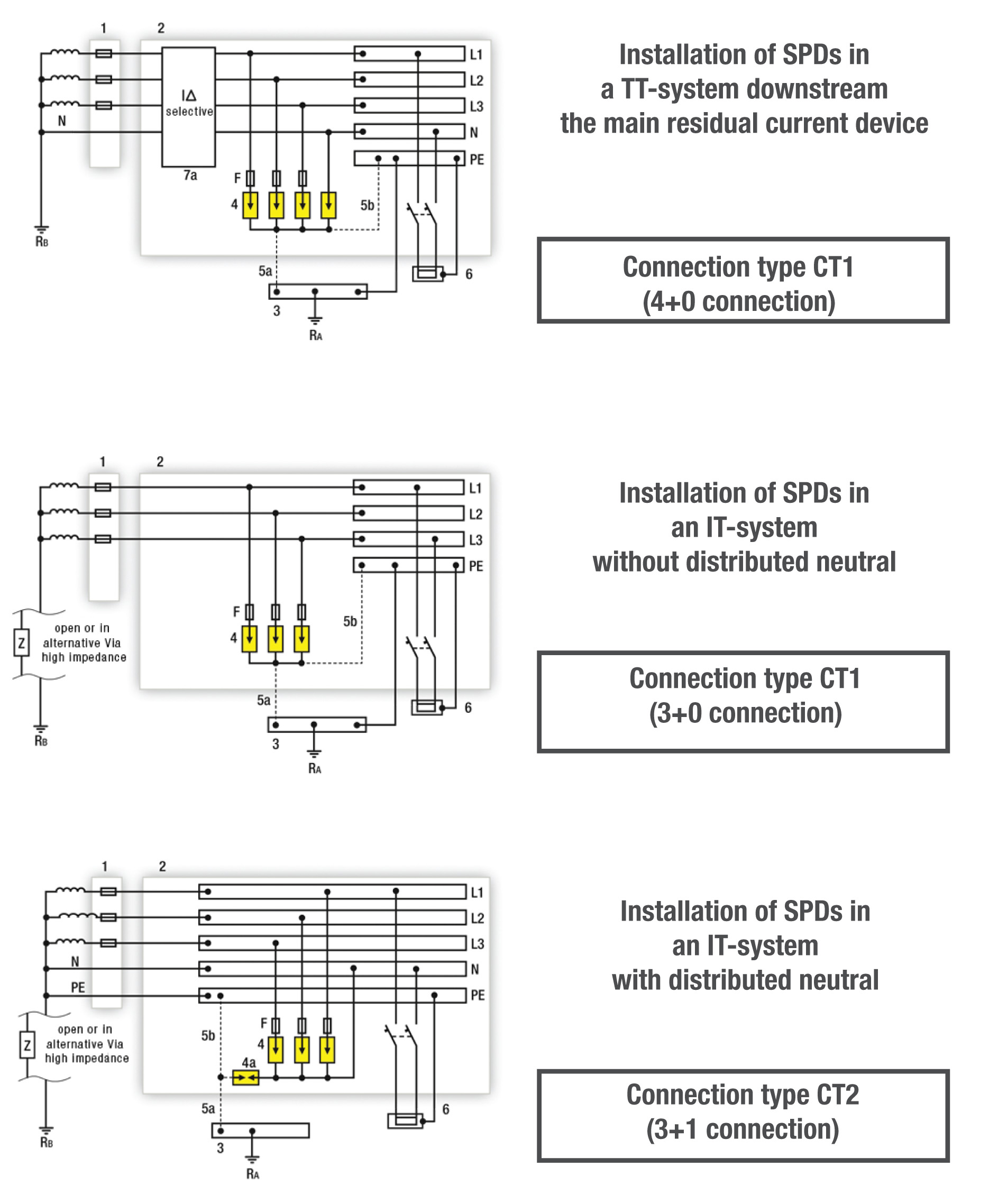
When the impulse current caused by a lightning strike is flowing through a conductor there is an electromagnetic field that could induce overvoltages on the adjacent conductors. By reducing the spiral windings of the cables, as indicated in the next pictures (light yellow area), the wiring is optimised.


installationadvices 3


ZOTUP

when the impulse current caused by a lightning strike is flowing through a conductor there is an electromagnetic field that could induce overvoltages on the adjacent conductors. By reducing the spiral windings of the cables, as indicated in the next pictures (light yellow area), the wiring is optimised.

installationadvices 4


The operation of surge arresters in an electrical system can be compromised, completely or partially, by the use of inappropriate conductor cables. The standard IEC 60364-5-534 offers important information about minimizing the voltage loss in the cables. To understand the importance of this issue, consider that the impulse current due to a lightning strike can increase at 10 kA/μs. In this instance the inductive components of circuit become dominant and can result in a voltage drop of 1 kV per meter.

installationadvices 5


The ‘V’ connection in many surge arresters is facilitated by the presence of doubled terminals. In some instances, this type of connection is not possible because of the associated high current and the relative cables cross-section. It is possible to optimise the wiring thanks to the CP series accessories.

installationadvices 6


ZOTUP – EASIER AND QUICKER SETUP WITH A GREAT PERFORMANCE

ZOTUP is a new range of surge protection devices with advanced performance, that has an easier and quicker setup for time and money saving. At ZOTUP we care for the needs of our customers and that’s why we created this new range giving you the chance not to use fuses. This means quicker setup, smaller footprint and less money spent but without giving up great performance and reliability.
This is what makes us stand out.

Installation of SPDs in TN-, TT-, and IT-Systems according to HD 60364-5-534

The installation of SPDs in a specific power distribution system must be coordinated with the protective measures against indirect contact (fault protection) and with the corresponding protective devices and their capability to withstand impulse currents.
This coordination depends on the type and earthing arrangement of the power system, as there are TN-, TT- and IT-systems according to HD 60364-1 and the corresponding protective devices may be:
• overcurrent protective devices;
• residual current protective devices;
• insulation monitoring devices.

spds installation in tn, tt and it systems


1: OCPD 1 OverCurrent Protective Device at the origin of the installation (e.g. in the main distribution board)
2: Main Distribution Board (MDB)
3: Main Earthing Terminal
4: Surge Protective Device(s) (SPDs)
4a: Surge Protective Device connected N to PE (N-PE SPD) when connection type CT2 (3+1 connection) is applied
5a/5b: Alternative connections to PE (preferably the shortest route, or even both connections as required in some countries)
6: Equipment to be protected
7: Residual Current Device (RCD) (in most cases this will be a RCCB or a RCBO)
7a: Selective Residual Current Device (e.g. type S RCD)
F: OCPD 2 OverCurrent Protective Device required by the SPD manufacturer
RA: Earthing resistance of the (consumers) installation
RB: Earthing resistance of the power supply system

spds installation in systems