
 Deutsch
 Français
 Italiano
Surge Protectors in Data Centers: Why They Are Essential


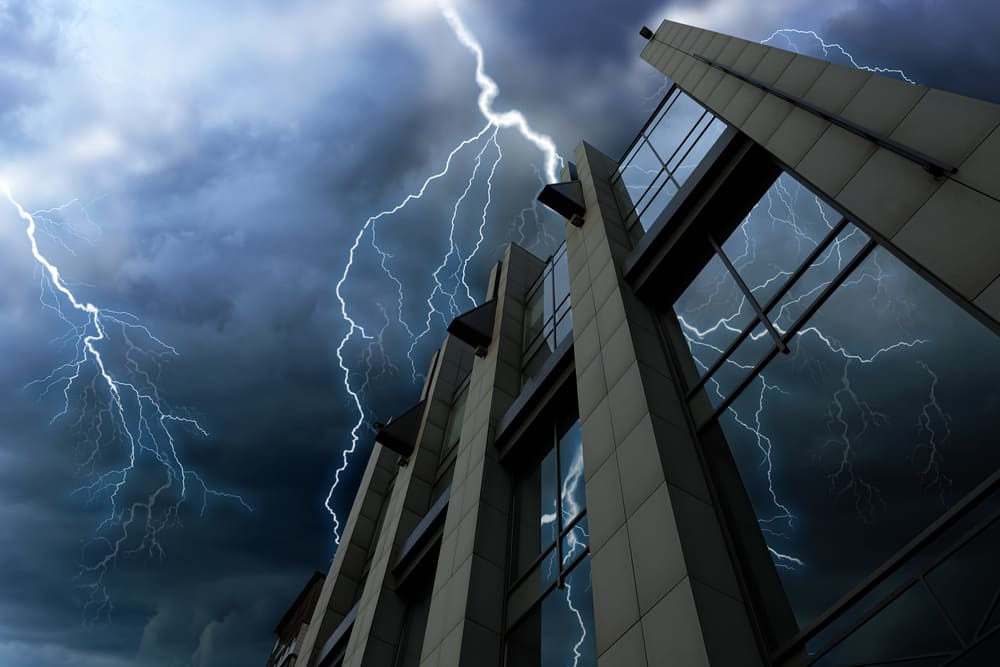
PROTECTION OF DATA CENTERS AGAINST LIGHTNING AND OVERVOLTAGES
Reducing downtime and preserving data integrity. The extent of damage resulting from Data Center outages requires the adoption of critical protection measures. Overvoltages of atmospheric origin are the cause of the most “catastrophic” events: protection is therefore indispensable.
EXTENT OF DAMAGE IN DATA CENTERS

The magnitude of costs associated with failures (blackouts) in Data Centers has made it necessary to conduct specific studies addressing this issue. In the United States and the United Kingdom, statistical tabulation of these costs has been active for several years and is generally expressed as Loss per Record. As early as 2010, the Ponemon Institute of Michigan quantified the Loss per Record at €215. The total loss associated with the most severe recorded event was quantified at 625,000 €. The same Institute, by analyzing in detail 51 cases of blackouts in low/medium-sized Data Centers operating across 15 different sectors, including Industrial and Tertiary sectors, found that in the event of downtime the average recovery time is approximately 130 minutes, with a cost to the company that can reach €480,000, corresponding to a loss of 3,690 € per minute. For companies operating in the Telecommunications and e-commerce sectors, losses may reach up to 8,000 € per minute. These figures speak for themselves and clearly explain why protection must be implemented at the highest possible level and taken into serious consideration from the design phase onward.
SOURCES OF DAMAGE
Direct lightning strikes are the primary sources of devastating destructive effects; indirect discharges and conducted high-frequency electromagnetic disturbances are the sources of numerous damages whose origin is not easily identifiable, yet whose effects are equally severe for systems in which operational continuity is essential. All these phenomena must be properly intercepted in order to protect installations connected to the power network and thus ensure their integrity and indispensable continuity of operation. This aspect is particularly relevant when the equipment to be protected consists of servers installed within Data Centers, data processing centers (DPC), telecommunications systems, or DCS systems for the supervision and control of industrial processes, where service continuity and data integrity are critical requirements. In light of these issues, it is essential to install surge protection devices (SPD) in such systems that are designed not only to protect against direct or indirect discharges, but also capable of addressing all safety and operational continuity issues that may arise at their end of life or simply due to natural degradation during their operational duty. To achieve this, it is necessary to select and install SPDs with high performance across all their parameters. Underestimating or trivializing this problem can lead to catastrophic events. This is a topic that must be addressed exclusively with specialists in lightning and overvoltage protection.
Would you like to explore further or receive support?
PARAMETERS FOR SIZING AND SELECTION OF SPDs
To better understand what is meant by the “high level of performance” required for these protection devices (SPD) against overvoltages, high-frequency electromagnetic disturbances, and to withstand stresses generated within the power supply network itself (such as switching overvoltages and temporary overvoltages TOV caused by insulation faults in MV and LV systems), it is essential to analyze and evaluate the following parameters:
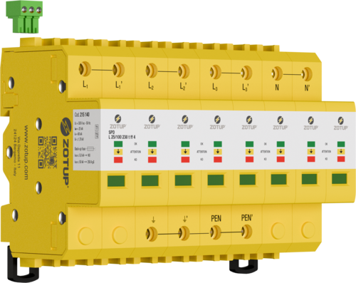 SPD Type 1+2 Three-phase with Neutral Model L 25/100 230 t ff 4 | 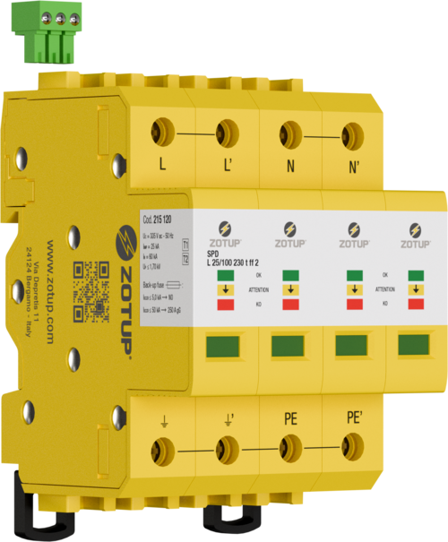 SPD Type 1+2 Mono-phase Model L 25/100 230 t ff 2 |
- magnitude of overvoltages and overcurrents of atmospheric origin, switching, and TOV;
- protection levels with respect to different magnitudes of impulse currents and their waveform shapes;
- short-circuit current withstand capability;
- behavior characteristic under temporary overvoltages; UTOV;
- response time;
- progressive monitoring of the SPD degradation level and consequent preventive alarm signaling.
The above-mentioned points, optimized into SPDs type 1+2, are examined individually below.
OVERVOLTAGES AND OVERCURRENTS OF ATMOSPHERIC AND SWITCHING ORIGIN
SPDs, depending on the parameters of the lightning current they are required to conduct to earth, are tested and therefore classified differently in accordance with standards IEC 61643-01 (2024-12) and IEC 61643-11 (2025-06), which classify them as follows:
- Type 1 SPDs: tested with impulse current Iimp (10/350 μs);
- Type 2 SPDs: tested with nominal discharge current In (8/20 μs);
- Type 3 SPDs: tested with a combined generator applying an open-circuit voltage Uoc (1,2/50 μs) and, under short-circuit conditions, a prospective current Icw (8/20 μs).
TEMPORARY OVERVOLTAGES (TOV)

Temporary overvoltages, also referred to as TOVs, are characterized by two parameters: time and magnitude. The duration primarily depends on the type of earthing system of the power supply network (this includes both medium- and low-voltage systems), while the magnitude U depends on the maximum continuous operating voltage of the low-voltage power supply system. It is important that the SPD behavior characteristic under TOV conditions is one of “withstand capability” rather than mere “safety,” which in practice accepts end-of-life of the surge protective device under such circumstances. In order for the SPD to withstand these possible network faults without damage, whether generated on the MV or LV side, the maximum continuous operating voltage of the SPD Uc must be at least 335 V for a 230/400 V ac system.
PROTECTION LEVEL
The protection level offered by the SPD system must be coordinated with the impulse insulation withstand voltage of the equipment to be protected, also referred to as the withstand level. The protection level as a function of the user’s immunity, also referred to as immunity level, must be coordinated with the impulse voltage that causes malfunctions, errors, or failures of the equipment to be protected. In the case if withstand level, verification is carried out using a generator with a minimum impulse current Iimp 25kA (10/350 μs) and Up ≤1250 V.
The qualifying parameters relating to the protection level must be evaluated at a nominal discharge current In not less than 60 kA (8/20 µs) with Up ≤ 1700 V, at an impulse current Iimp not less than 25 kA (10/350 µs) with Up ≤ 1250 V, and at a low crest current value of 1 kA with Up ≤ 750 V. By complying with these values, sensitive equipment that conforms to the withstand and immunity levels required by the relevant standards is generally adequately protected.
SHORT-CIRCUIT CURRENT WITHSTAND
During its overvoltage protection function, in the SPD flows also the short-circuit current. The SPD must prevent the flow of follow current from the power network (NFC – No Follow Current) in order to avoid degradation during its normal protective operation. The value of the maximum short-circuit current at the installation point of the surge arresters Isccr depends on the installation, but in this application it generally does not exceed 50 kA rms.
RESPONSE TIME
The response time of the SPD is not addressed by product standard IEC 61643-11 Ed. 2 (2025-06). However, the damage times of the semiconductors present in electronic equipment make this a non-negligible aspect. Impulsive overvoltages occurring in the installation are on the order of microseconds, SPD response times are on the order of nanoseconds, while the damage times of certain semiconductors are on the order of picoseconds. This simple consideration leads to the conclusion that the higher the speed at which the SPD performs its protective function, the better its performance. A suitable response time value for this application is ≤ 25 ns.
PROGRESSIVE INDICATION OF THE SPD STATUS INDICATOR
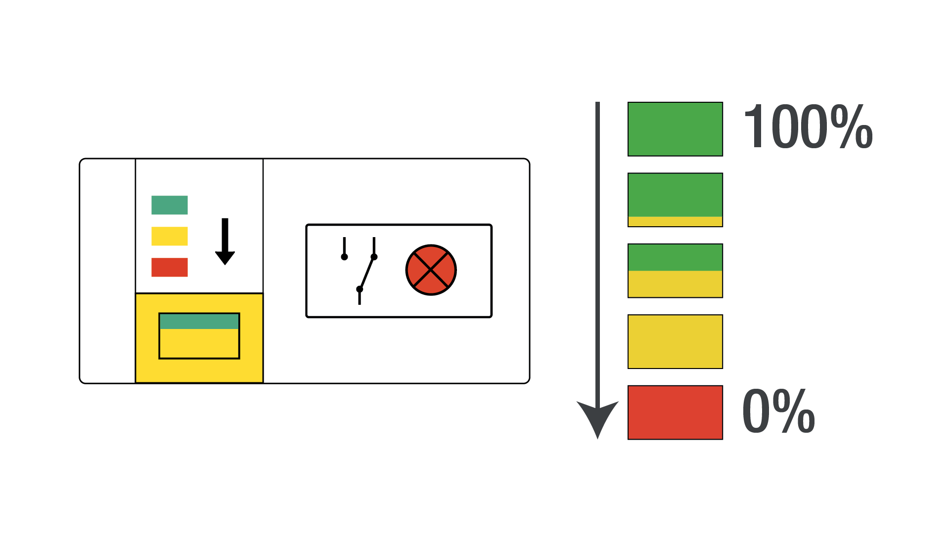
The activity of verifying the surge and lightning protection system, as required by CEI Guide 81-2 (2013-02), is essential not only for regulatory compliance but above all to ensure operational continuity and prevent possible catastrophic effects previously highlighted. This function is locally displayed by a change in color of the status indicator window. The transition from the initial green color (full performance) to the fully yellow color (minimum performance) occurs progressively. The color thus indicates the actual residual performance of the surge arrester, providing complete and necessary information compared to a simple end-of-life indication. The subsequent transition from yellow to red indicates that the surge arrester has reached end of life. The advantage of progressive indication of performance degradation allows maintenance personnel to optimize the decision regarding replacement. Surge arresters must be equipped with a changeover contact for remote alarm signaling. It is very important that the contact is activated when performance is reduced to the minimum level (fully yellow indicator) and not when the arrester has reached end of life (red indicator). The remote alarm is therefore preventive in nature: the surge arrester is still active and capable of providing protection, althougth with reduced performance.
USE OF SURGE ARRESTERS WITH PD3 IN ENVIRONMENTS WITH HIGH CONDUCTIVE POLLUTION (PD3)
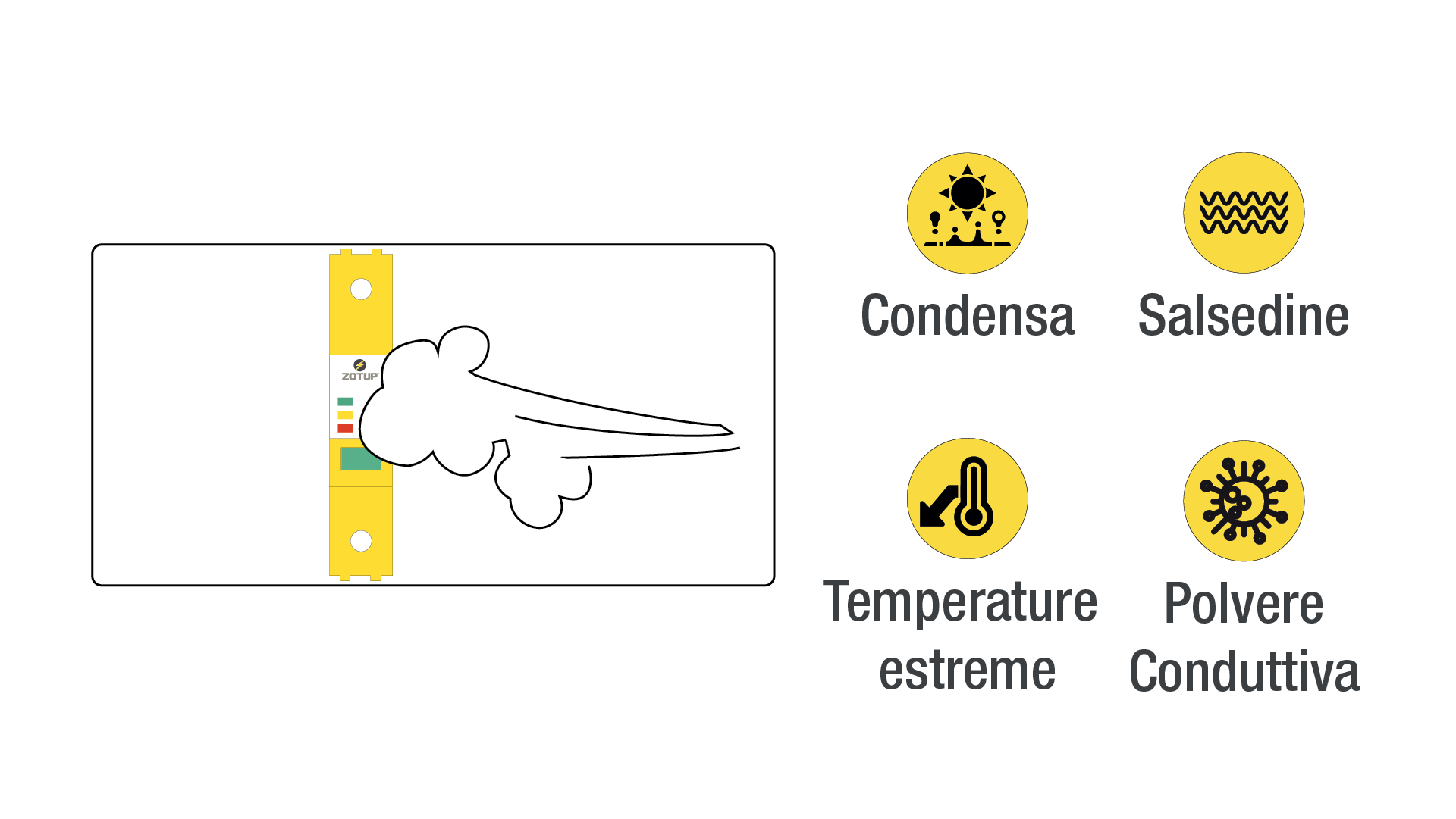
Electrical and electronic equipment in a Data Center is primarily located within temperature-controlled environments. However, it is often overlooked that air handling units (AHUs) are mainly installed outdoors, typically on rooftops. Air Handling Units (AHUs), which perform an essential function in a Data Center, are subject to natural condensation formation and therefore to conductive pollution. SPDs must also be evaluated for their ability to withstand these severe environmental conditions. Stringent requirements must be imposed with respect to conductive pollution. Pollution Degree 3, which represents the maximum applicable degree, satisfies this requirement. The standard internal insulation distances within the surge arrester, as well as the long-term ability of insulating materials to withstand electrical arc tracking, have proven inadequate. In line with the focus on operation in “critical” environments, the maximum operating temperature should also comply with the Temperature Extended Range classification.